
Conventional radiator
Hydronic panel radiators for boilers and heat pumps. Compare known reference outputs, dimensions and temperature-corrected estimates or supplied performance data.
Draw your home once, then calculate heat loss room by room, size radiators for boilers or heat pumps, and create underfloor-heating pipe layouts from the same geometry.
No retyping room dimensions into another calculator. Your floor plan becomes your heating model.
In the free planner, choose Tools → Heating Layout. Add thermal information to your measured floorplan; no account is required.
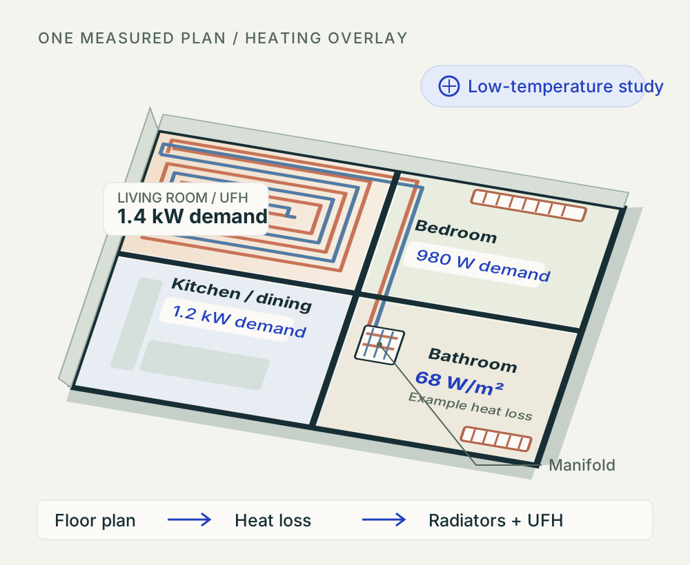
Start with the building, not a blank BTU form. Your room outlines, openings and heights become the geometric foundation for a heating layout.
Many standalone calculators ask you to enter length, width, height, window sizes, external walls and floor area again for every room. A heat loss calculator from a floor plan can reuse the geometry you have already drawn, including connected rooms and irregular outlines.
FreeFloorplan3D uses the same measured plan for floorplanning, electrical layout and heating planning. Add construction and insulation information, indoor targets, the external design temperature and ventilation assumptions. Geometry tells the tool how much surface there is; thermal inputs explain how that surface loses heat.
Room shapes, heights and openings.
Geometry plus thermal inputs.
Match output to each room.
Review, edit and keep your plan.
A useful room by room heat loss calculator looks beyond floor area. Heating Layout uses the drawn room geometry with your thermal inputs to estimate losses through walls, windows, doors, floors and roofs or ceilings, plus ventilation and infiltration.
Review which walls are external, shared with a heated room or adjacent to an unheated space. Confirm the floor and ceiling boundaries too. A shared partition is not automatically an external heat-loss surface. Keep uncertain construction and ventilation inputs visible.
The result is a heating requirement in watts per room, with a W/m² view that makes rooms easier to compare. Use the whole-property summary as a whole house heat loss calculator for the rooms in your plan, then return to the room breakdown to understand what is driving the total.
For a home heat loss calculation, a colder external design condition, more exposed glazing or a different insulation assumption can change the answer substantially. Review inputs before choosing an emitter—not just the final number.
The preliminary fabric calculation uses surface area × U-value × temperature difference. Ventilation uses room volume, air changes per hour and temperature difference. Presets are editable assumptions; any design allowance should be shown separately. This is not a claim of certified BS EN 12831 compliance.
For professional context, see the Energy Saving Trust’s room-by-room heat-loss guidance.
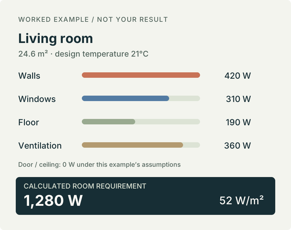
“What size radiator do I need?” starts with room demand and operating temperature—not just a room’s length and width.
The radiator sizing calculator compares the calculated room heat loss with candidate radiator outputs at your chosen system temperatures. A radiator calculator from room size alone cannot distinguish a well-insulated bedroom from a similarly sized room with extensive glazing.
Enter known reference ratings or suitable manufacturer performance information. Compare radiator types and dimensions, then place the selected radiator on the plan and move it along the wall. Check available wall length, doors, furniture and mounting space as well as thermal coverage.
Read the radiator output calculator in watts alongside the required watts for that room. A nominal catalogue rating is only useful when its test conditions are understood. Missing product information should remain an unknown, not a confident recommendation.
Hypothetical candidate, not a product recommendation. Actual output needs verified rating or performance information.
A radiator can meet the room demand at boiler temperatures and fall short at lower water temperatures. See the difference before agreeing an upgrade.
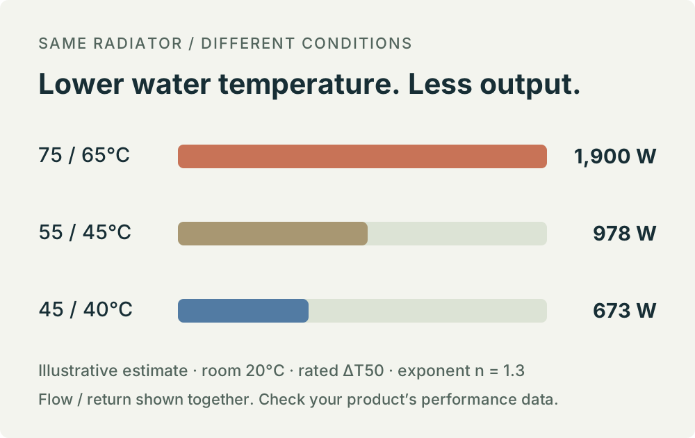
Use the heat pump radiator sizing calculator to compare room demand with output at the proposed flow and return temperatures. The same panel has less temperature difference from the room at 45/40°C than at 75/65°C, so it transfers less heat.
When comparing radiator output at 45 degrees—or radiator sizing at 55°C—specify the return and room temperatures too. Flow temperature on its own does not define the radiator’s output.
Switch temperature scenarios and review which rooms need larger radiators, a supported hybrid emitter, UFH or improvements to the building fabric. A low temperature radiator calculator should reveal a shortfall, not silently assume the original catalogue output still applies.
For the conventional radiator estimate, ΔT is mean water temperature minus room temperature. It is not the flow-to-return temperature drop. At 45/40/20°C it is 22.5 K. The example uses 1,900 × (22.5 / 50)1.3 ≈ 673 W. Use the product’s exponent or supplied performance data where available.
See Stelrad’s radiator temperature-correction guidance for manufacturer context.
Use the same calculated requirement to compare conventional hydronic, direct electric and supported fan-assisted heating options.
Hydronic panel radiators for boilers and heat pumps. Compare known reference outputs, dimensions and temperature-corrected estimates or supplied performance data.
Use the electric radiator size calculator to compare direct electric capacity with room demand. Resistive heating is not subject to a water-temperature correction. Electrical circuit provision needs a separate check.
Compare hydronic emitters with electrically powered fans or thermal activators where manufacturer performance information is supplied. Check output at the selected fan mode and temperatures rather than treating it as a standard panel.
Here “hybrid” means a fan-assisted heat emitter, not a hybrid boiler-and-heat-pump system. Keep product information with the project.
The underfloor heating planner starts with your actual room outline, manifold position and exclusions—not a second rectangle typed into a form.
Use the same floorplan to plan rectangular, L-shaped, T-shaped, U-shaped and irregular rooms, including recesses. Mark fixed cabinets, a kitchen island, a bath or other areas that should not be treated as active heated floor.
Choose pipe spacing, a boundary offset, bend constraints, a pattern and a suitable maximum circuit length. Generate the pipe layout, then review every circuit and its routes to the manifold. Automatic spirals currently suit suitable rectangular rooms without exclusions. Complex shapes or exclusions may use an explicitly reported serpentine fallback; restrictive settings can require manual refinement or prevent a valid route from being generated.
A geometry-based UFH layout planner lets you see where the heating actually goes. It also makes visible the decisions a simple underfloor heating room calculator can hide: what area is excluded, where the manifold sits and how much pipe is used getting to it.
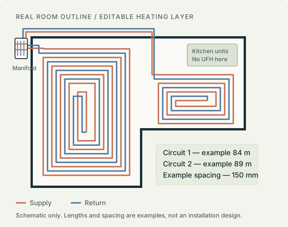
Geometry can tell you a route length. Supported system performance data tells you how much heat the floor can deliver.
The underfloor heating pipe length calculator uses active floor area, spacing, pipe settings, manifold location and generated paths. Include both supply and return tails when reviewing each circuit.
A UFH loop calculator or circuit length calculator is most useful when the result remains tied to an inspectable drawing. Show any additional wastage separately.
UFH output in watts per square metre depends on floor construction, covering resistance, spacing, water temperatures and the selected pipe system. It is not one universal number.
If a suitable performance dataset is missing or conditions are outside its supported range, output must remain unconfirmed. A valid pipe layout alone does not prove the floor meets the room heat loss.
Use an underfloor heating pipe spacing calculator as part of the system comparison, not as an automatic instruction to install a particular spacing. Follow the chosen system’s manufacturer guidance and professional design.
A generated layout is a starting point for review, not a locked image. Refine pipe routes with editing controls, move the manifold, adjust exclusions or spacing, and regenerate the affected room rather than redrawing the property.
Review split circuits and lock layouts you want to retain. Choose spiral or serpentine routing where the geometry and settings support it. After a manual edit, check lengths, bends, clearances and manifold connections again.
Keep the main room geometry separate from the heating layer. A heating layout change should not silently resize the room just to make the pipes fit.
Follow the five-step workflow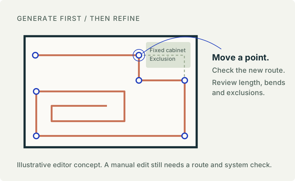
A home heating layout planner should let rooms have different solutions. Compare each room demand with the supported emitter capacity.
| Room | Heat loss | UFH capacity | Additional heating |
|---|---|---|---|
| Living room | 1,800 W | 1,650 W | 150 W shortfall |
| Kitchen | 1,250 W | 1,400 W | None in this example |
| Bedroom | 900 W | Not selected | 900 W radiator demand |
Use the radiator and underfloor heating calculator together to explore a mixed system: UFH in a living space, radiators in bedrooms or an electric emitter in a separate room. Where UFH falls short, consider an additional emitter or fabric improvements and compare supported outputs again.
Capacity shown on a plan does not coordinate the hydraulics. Flow rates, controls, temperature requirements, pipework and heat-source selection must work together in the final system design.
Keep the room demand visible while you change system temperatures. Lower-temperature performance is a room-by-room question.
For heat-pump heating planning, test different flow and return values and compare each emitter with the room requirement. A radiator output at 40 degree flow temperature depends on the chosen return and room temperatures; UFH needs suitable floor-system data too.
These are comparison scenarios, not universally recommended settings. Use the same home renovation heating plan to explore the effect of better insulation, different emitters or a revised floor covering, then discuss the practical system with your heating professional.
The Energy & Insulation Planner explains how to compare U-values, insulation thickness and heat loss before and after fabric upgrades. Review the revised thermal inputs before rechecking your emitters.
Use the existing 2D and 3D planner. There is no separate heating application and no need to redraw the property.
Add walls, doors, windows, heights and dimensions, or open an existing project. The room floor plan walkthrough and whole-house planning guide help you establish reliable geometry.
Open Tools → Heating Layout. Review construction, insulation, boundary conditions, ventilation and indoor/outdoor design temperatures. Select the flow and return values you want to test.
Review each room’s surface and ventilation losses and the whole-property total. Resolve questionable inputs before relying on the results.
Compare conventional, electric or supported hybrid radiators, UFH or a combination. Keep radiator ratings and any UFH performance dataset with the project.
Place radiators or generate and refine UFH circuits. Review room coverage, routes, quantities and warnings. Save a project backup and bring the proposal to your heating professional.
Select a stage or play the short illustration. Example values are not a calculation of your home.
Stage 1: the measured floor plan is the shared geometry.
Heat-loss assumptions, radiator temperatures and the difference between a UFH route and verified system performance.
Start with measured room geometry, openings, ceiling height, construction information and indoor and outdoor design temperatures. The planner estimates losses through the building surfaces and ventilation, then shows the room requirement in watts and watts per square metre. Check the assumptions and any design allowance rather than treating a room-size rule of thumb as a complete calculation.
Yes. The Heating Layout workflow reuses the room outlines, heights, doors and windows in your floorplan. Add thermal properties, boundary conditions and design temperatures to turn that geometry into a preliminary heating model. You do not need to enter every room length and width again in a separate calculator.
Yes. Review each room separately, then use the whole-property summary to see the combined design requirement for the rooms included in the project. Check shared walls and adjacent-space assumptions. A heating requirement for the rooms is not by itself a complete heat-pump selection, hot-water design or seasonal energy-use forecast.
Yes, for preliminary planning with appropriate UK project inputs. Enter the relevant external design temperature, room targets, construction values and ventilation assumptions. A postcode label alone does not determine the local weather design condition. Defaults are editable assumptions, not a measured survey or a certified calculation.
Use the room design heat requirement in watts, then check the radiator output at your chosen flow, return and room temperatures. Compare candidates with known reference ratings or supplied performance data. The radiator must both cover the thermal requirement and physically fit the wall; a room area or radiator width alone cannot establish its output.
Calculate the room heat loss first. Set the intended heat-pump flow and return temperatures, then compare the corrected or manufacturer-supplied radiator output with that demand. At lower water temperatures you may need a larger emitter, fan-assisted radiator, suitable UFH system or fabric improvements. Have the final choice and hydraulic design checked by your heating professional.
Less temperature difference between the radiator and room air means less heat transfer. Both the return temperature and room temperature matter, not just the flow setting. Conventional panel-radiator estimates use a reference rating, temperature difference and exponent; supplied manufacturer performance data is preferable where available.
Yes, when you know their dimensions and relevant output data. Add the existing emitters, enter their reference ratings or performance information, and compare their output with each room demand at the proposed system temperatures. A missing or uncertain rating should remain an unknown, not an assumed pass. Pipework, flow, controls and heat-pump suitability still need a separate system check.
There is no universal setting. The appropriate design temperatures depend on the property heat loss, emitter performance, equipment and hydraulic design. Test alternatives such as 55/45, 45/40 or 40/35°C as scenarios, then agree the final operating arrangement with a qualified heating professional. Weather compensation may change operating temperatures as conditions change.
Yes. Direct electric heating is sized against the room demand without a water-temperature correction. Here, hybrid means a hydronic emitter with electrically powered fans or thermal activators, not a combined boiler and heat-pump system. Hybrid output needs suitable manufacturer performance points at the chosen temperatures and fan mode; missing data should not be replaced by a generic panel-radiator estimate.
A first quantity estimate uses active heated area and spacing, but a drawn circuit gives a more useful route length. Add the heated-area pipe path plus the supply and return tails to the manifold. Review exclusions, routing and bends. Any installation wastage should be identified separately from the calculated geometric pipe length.
It depends on the room heat demand, water temperatures, floor construction, covering, pipe system and manufacturer performance information. Tighter spacing is not a universal answer. Use the UFH settings to explore options and compare supported output with demand, while respecting surface-temperature and system limits.
The allowable length depends on pipe diameter, hydraulic conditions, manifold arrangement and manufacturer guidance. Enter an appropriate circuit-length limit for the selected system and review the generated circuits, including their supply and return tails. There is no one maximum length suitable for all UFH systems.
The active floor area, spacing, generated pipe routes, manifold position and selected length limit determine the layout. Large or complex zones may need several circuits. Inspect the generated circuit lengths and warnings; circuit count alone does not establish that flows, pressure drop or balancing are suitable.
Compare supported heat output over the active heated area with the room heat loss. Fixed cabinets and other exclusions reduce that area. Output also depends on floor construction, covering and water temperatures. If performance data is missing, capacity is not confirmed. A shortfall may call for another emitter or fabric improvements, not simply a higher water temperature.
Yes. Plan the emitter choice room by room, including a radiator-and-UFH combination where useful. Compare each room demand with the supported emitter outputs. Your heating professional should design the circuits, controls and any different temperature requirements; a combined drawing is not automatic hydraulic coordination.
Review the generated paths and refine the layout using its editing controls. Adjust the manifold, exclusions, spacing or pattern and regenerate affected rooms as needed. Automatic spirals currently suit suitable rectangular rooms without exclusions; complex shapes may use a reported serpentine fallback. Manual edits and locked circuits still need checks for route length, boundary clearance, bends and system suitability.
Heating Layout is included in the FreeFloorplan3D free tier. Use the existing floorplan application for preliminary room heat loss, radiator sizing and UFH planning without purchasing a paid plan. Manufacturer performance information and professional design or installation services are separate from the free planning tool.
No account is required for the free planner. Open it in your browser, draw or open your floorplan and use Heating Layout. Keep downloaded project backups: a local browser draft is not automatic cloud storage, and private browsing or clearing site data can remove it.
The tool is designed for heating planning and preliminary sizing. Final system design, product selection, regulatory requirements and installation should be checked by a suitably qualified heating professional. The calculations and illustrations are not certified engineering documents or proof of MCS, BS EN 12831 or EN 1264 compliance.
Designed for heating planning and preliminary sizing. Final system design and installation should be checked by a suitably qualified heating professional.
By the FreeFloorplan3D team · Updated · AI-assisted content. Diagrams and figures are labelled examples, not certified calculations.